Configuring the Control Node with BGP
- date:
2020-03-18
An important task after a successful installation is to configure the control node with BGP. This procedure shows how to configure basic BGP peering between one or more virtual network controller control nodes and any external BGP speakers. External BGP speakers, such as Juniper Networks MX80 routers, are needed for connectivity to instances on the virtual network from an external infrastructure or a public network.
Before you begin, ensure that the following tasks are completed:
The OpenSDN Controller base system image has been installed on all servers.
The role-based services have been assigned and provisioned.
IP connectivity has been verified between all nodes of the OpenSDN Controller.
You have access to OpenSDN Web User Interface (WebUI). You can access the user interface at http://``nn.nn.nn.nn``:8143, where ``nn.nn.nn.nn`` is the IP address of the configuration node server that is running the OpenSDN service.
These topics provide instructions to configure the Control Node with BGP.
Configuring the Control Node from OpenSDN WebUI
To configure BGP peering in the control node:
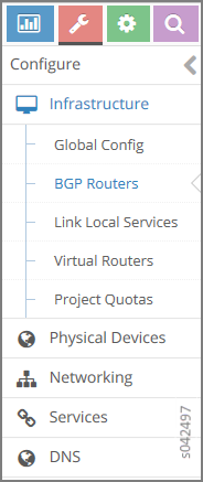
From the OpenSDN Controller module control node (http://``nn.nn.nn.nn``:8143), select .
A summary screen of the control nodes and BGP routers is displayed; see.
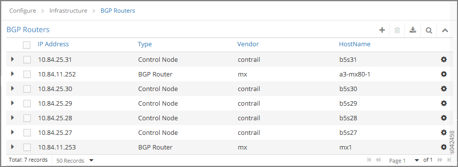
(Optional) The global AS number is 64512 by default. To change the AS number, on the BGP Router summary screen click the gear wheel and select Edit. In the Edit BGP Router window enter the new number.
To create control nodes and BGP routers, on the BGP Routers summary screen, click the
 icon. The Create BGP
Router window is displayed.
icon. The Create BGP
Router window is displayed.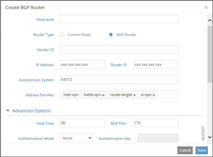
In the Create BGP Router window, click BGP Router to add a new BGP router or click Control Node to add control nodes.
For each node you want to add, populate the fields with values for your system.
Table 1: Create BGP Router Fields
Field
Description
Hostname
Enter a name for the node being added.
Vendor ID
Required for external peers. Populate with a text identifier, for example, “MX-0”. (BGP peer only)
IP Address
The IP address of the node.
Router ID
Enter the router ID.
Autonomous System
Enter the AS number in the range 1-65535 for the node. (BGP peer only)
Address Families
Enter the address family, for example, inet-vpn
Hold Time
BGP session hold time. The default is 90 seconds; change if needed.
BGP Port
The default is 179; change if needed.
Authentication Mode
Enable MD5 authentication if desired.
Authentication key
Enter the Authentication Key value.
Physical Router
The type of the physical router.
Available Peers
Displays peers currently available.
Configured Peers
Displays peers currently configured.
Click Save to add each node that you create.
To configure an existing node as a peer, select it from the list in the Available Peers box, then click >> to move it into the Configured Peers box.
Click << to remove a node from the Configured Peers box.
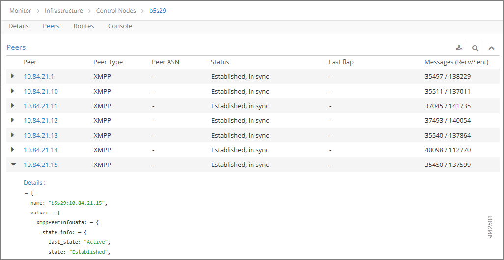
You can check for peers by selecting .
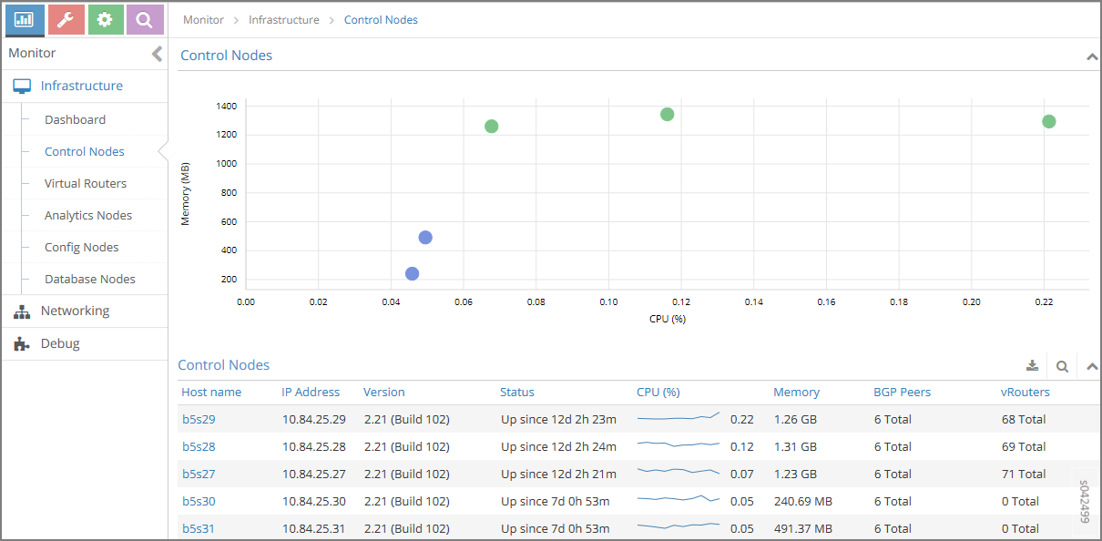
In the Control Nodes window, click any hostname in the memory map to view its details.
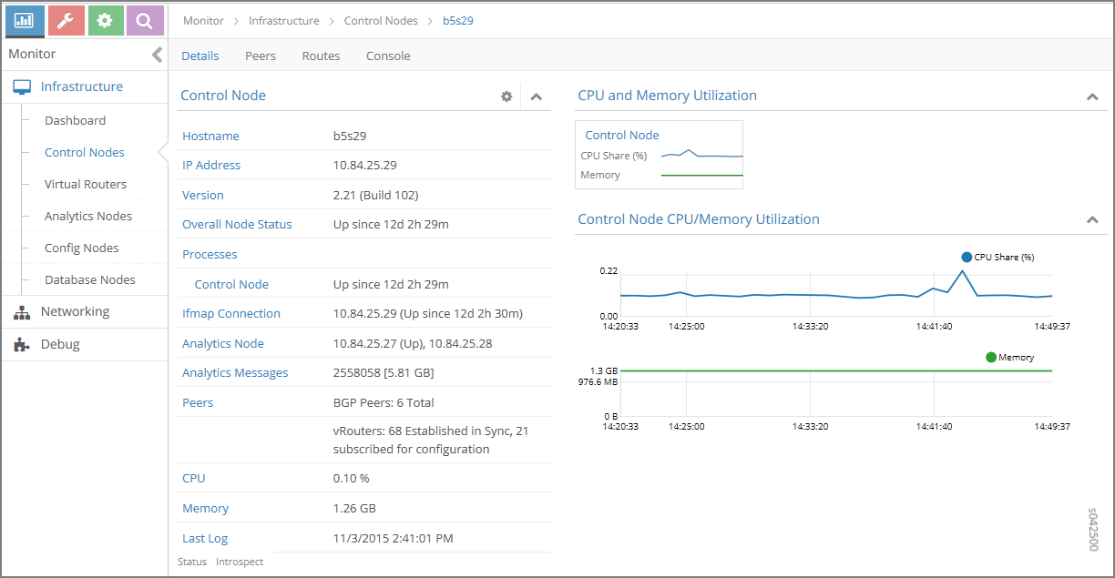
Click the Peers tab to view the peers of a control node.